Snaps
Snaps and Cursor Control
There are a number of drawing aids available to you while designing that can help you insert elements easily and precisely. Conveniently located in the lower right corner of the screen, these 7 handy tools can be turned on and off as needed.
SNAPTRACK
The Snap Tracking feature helps you draw objects at specific angles or positions relative to other objects. When snap tracking is turned on, temporary alignment paths appear that are based on object snap points, such as endpoints and midpoints. Such points are marked with a small, solid square when you move your cursor over their drawing paths. You can acquire points on up to five elements at one time. Alignment paths are horizontal and vertical, and can also be angled if your Angle Snap is turned on. Snap tracking can be turned on and off as needed. In order for snap tracking to work, the Object Snap (OBJSNAP) must be enabled. Snap tracking is available in both Model View and Worksheet View.
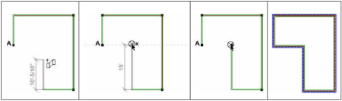 Let’s say in the following example that we want the end of the wall being drawn to be in alignment with point A. When you hover over point A and then stretch your wall towards the drawing path of point A, a horizontal dotted line appears indicating the path of alignment with point A. This makes it easy to select an end point for the wall that is aligned with point A.
To turn Snap Tracking on or off:
Press F3 on your keyboard, or
Click on the Status bar, or
Select Settings > Program Settings > Drawing Aids, then check or uncheck the Snap Tracking (F3) check box
GRIDSNAP
The Grid Snap feature snaps your pointer to an invisible grid when inserting elements. By default, the spacing between the grid lines in the invisible grid is 4′, but you can change this if you want. If you enable the Match Grid option, the invisible snap grid becomes the same size as the drawing grid. This will make it seem like you are snapping to the drawing grid while drawing.
To set up a snap grid:
Select Settings > Program Settings or click on the Settings toolbar.
In the Program Settings dialog, select Drawing Aids in the left column.
To turn the grid snap on, enable the Grid Snap (F4) check box.
If you want the snap grid to be the same size as the drawing grid, check the Match Grid check box in the Grid Snap
To specify a custom distance between vertical grid lines, enter a value in the X Spacing edit box.
To specify a custom distance between horizontal grid lines, enter a value in the Y Spacing edit box.
Click OK.
To turn the Grid Snap on or off:
Press F4 on your keyboard, or
Click on the Status bar, or
Select Settings > Program Settings, then on the Drawing Aids pane, check or uncheck the Grid Snap (F4)check box in the Snap Behavior area
OBJSNAP
When inserting an element, the Object Snap feature makes your cursor automatically snap to common points on existing elements in your drawing. This allows you to select an insertion point or start point more easily and precisely. When the Object Snap is turned on, the Endpoint, Midpoint, Nearest and Perpendicularsnaps become active. Your cursor icon changes when your cursor comes close to a snap point, providing a visual indicator that snapping is occurring.
Snap Cursor
This tool is essential when drawing walls that intersect other walls. Always wait to see the OBJSNAP cursor change to ensure that a clean intersection is formed.
To turn the Object Snap on or off:
Press F5 on your keyboard, or
Click on the Status bar, or
Select Settings > Program Settings, then on the Drawing Aids pane, check or uncheck the Object Snap (F5) check box in the Snap Behavior area
ANGLESNAP
When the Angle Snap feature is turned on, your cursor snaps to specific angles when rotating an element. If you set your snap angle to 10º, for example, your cursor will snap at 10º intervals as you rotate the element.
By default, the Angle Snap is on and is set to 15º.
Note: Ortho will override Angle Snap, so make sure Ortho is disabled when using Angle Snap.
To turn the Angle Snap on or off:
Press F6 on your keyboard, or
Click on the Status bar, or
Select Settings > Program Settings, then on the Drawing Aids pane, check or uncheck the Angle Snap (F6) check box
To change the snap angle:
Select Settings > Program Settings or click on the Settings toolbar.
In the Program Settings dialog, select Drawing Aids in the left column.
In the Snap Behavior area, type the desired snap angle in the Snap Angle edit box, or use the arrows to scroll up or down through a list of values.
Click OK.
GRID
A drawing grid is simply a set of horizontal and vertical lines that can help you orient objects to one another. By default, the spacing between grid lines is 4’, but you can change this if you want. You can also control the color and style of the grid. Note that the drawing grid is a visual aid only, and will not be included in printouts. By default a grid is displayed in the drawing area, but you can turn it off if you like.
To set up a drawing grid:
Select Settings > Program Settings or click on the Settings toolbar.
In the Program Settings dialog, select Drawing Aids in the left column.
In the Grid area, check the Enable (F7) check box.
Click the Color swatch, then select a color for the grid from the Color
From the Style drop box, select a style for the grid — Dots or Lines.
Specify the desired distance between vertical grid lines in the X Spacing edit box.
Specify the desired distance between horizontal grid lines in the Y Spacing edit box.
By default, the grid is 160’ x 160’, which is the default size of the terrain. To change the overall size of the grid, enter the desired width in the X Limit edit box, and the desired height in the Y Limit edit box.
Click OK.
To turn the Grid on or off:
Press F7 on your keyboard, or
Click on the Status bar, or
Select Settings > Program Settings, then on the Drawing Aids pane, check or uncheck the Enable (F7)check box in the Grid area
ORTHO
The Ortho feature restricts your cursor movement to 90-degree angles when you are inserting elements. This can be especially helpful when inserting line-drawn elements like walls. By default, Ortho is enabled. If you want to draw a wall or line at a non-orthogonal angle, you must disable Ortho.
To turn Ortho on or off:
Press F8 on your keyboard, or
Click on the Status bar, or
Select Settings > Program Settings, then on the Drawing Aids pane, check or uncheck the Ortho (F8)check box
COLLISION
The program’s intelligent Collision Control feature prevents objects from being inserted where they do not fit. If you are trying to insert an object and find that it will not move into the area where you want it to go, Collision Control is detecting that it will not fit or that there is just enough room. If you still want to insert the element in that area, you need to disable Collision Control.
By default, Collision Control is on, but you can turn it off whenever you like using one of three methods.
To turn Collision Control on or off:
Press F9 on your keyboard, or
Click on the Status bar, or
Select Settings > Program Settings, then on the Building Aids pane, check or uncheck the Enable Collision Control (F9) check box
Note: Collision control affects building elements on the current building location only. It does not affect landscape elements.